Vibration Monitoring Systems: Condition-Based Maintenance
A vibration monitoring system continuously captures vibration signals from rotating equipment and uses trends and thresholds to detect the early signs of bearing, gear and imbalance faults, so maintenance moves from fixed-interval inspection to repair based on the equipment's actual condition. It addresses one specific problem: a machine fails suddenly before its planned shutdown while routine checks still show nothing abnormal. A workable system depends less on the sensors themselves than on how measurement points are chosen, how thresholds are tiered, and how data is turned into maintenance work orders.
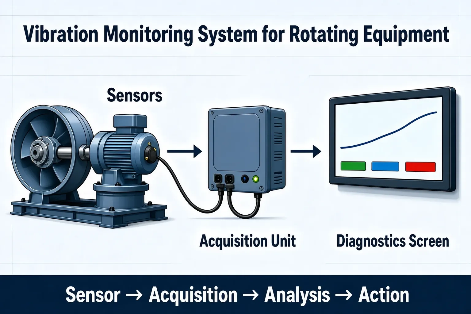
Why vibration is a good early indicator for rotating equipment
Most mechanical faults on rotating equipment have a vibration signature. Damaged bearings, abnormal gear meshing, rotor imbalance and coupling misalignment all leave a change in the vibration spectrum well before temperature rises or noise becomes noticeable. Scheduled inspection relies on hearing and touch, so by the time a problem is detected the degradation is often already advanced. Continuous vibration acquisition moves the decision point back to before the fault fully develops.
Vibration monitoring does not replace engineering judgement; it automates the question of when to look, and diagnostic conclusions still need review by an engineer.
The four parts of a vibration monitoring system
A workable system is usually split into sensing, acquisition, analysis and action layers. Remove any one and the loop does not close.
- Sensing: accelerometers (velocity sensors for lower-speed machines) mounted on rigid points of the bearing housing or casing
- Acquisition: on-site acquisition units or edge gateways handling synchronous sampling, buffering and store-and-forward after network loss
- Analysis: time-domain indicators (velocity RMS, acceleration envelope) and frequency-domain analysis, published as trend curves
- Action: tiered thresholds triggering alarms that are routed into inspection or maintenance work orders
How to lay out measurement points
More points is not better. A common approach sets density by equipment criticality and fault impact: key machine trains get one point at each of the drive-end and non-drive-end bearings, while auxiliary machines can be covered with a single summary point per train. Axial and radial directions should be considered separately, because misalignment and imbalance show up differently in each direction.
| Equipment type | Suggested point location | What to watch |
|---|---|---|
| Fans / induced draft fans | Drive-end bearing, non-drive-end bearing | Imbalance, bearing damage |
| Pumps / pump sets | Motor-end and pump-end bearings | Cavitation, misalignment |
| Gearboxes | Input shaft and output shaft bearings | Gear meshing, bearings |
| Compressors | Main shaft bearings, casing | Looseness, impact-type symptoms |
Setting thresholds and tiered alarms
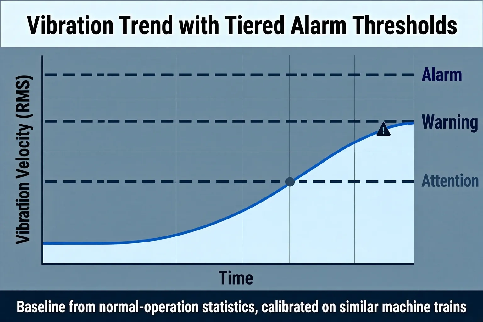
Thresholds should not be copied directly from generic values in equipment manuals, which are usually shutdown protection limits rather than early warning limits. A common engineering approach uses three tiers: attention, warning, alarm. The baseline comes from measurements taken over a period of normal operation, then calibrated against historical data from similar machine trains. Trends matter more than single-point values: the same vibration level is a very different priority when it is stable versus rising quickly.
Turning vibration data into maintenance action
Data only becomes action when the handling rules are explicit, otherwise alarms gradually get ignored.
- After an alarm fires, check trend direction and duration first to rule out short-term fluctuation from operating changes
- Once confirmed, dispatch by equipment criticality, with key machine trains on immediate response
- Record the action taken and the reset time after repair, and write it back into the equipment file
- Review false positives and missed alarms periodically to recalibrate thresholds
Information to prepare before implementation
Clarifying the equipment list and operating conditions before the system is introduced reduces later rework. At minimum, confirm the equipment register and criticality ranking, the mountable location on each machine, whether existing PLCs or instruments can supply related signals such as speed, and whether the plant network allows acquisition units to connect. For older machines, point locations and wiring conditions often take more time than the software itself.
Shanghai Orpaon Intelligent has over a decade of project experience in industrial data acquisition and monitoring systems, including monitoring systems delivered for rotating equipment and test benches, and can jointly confirm point layouts and threshold definitions according to on-site conditions.
Summary
The value of a vibration monitoring system is that it changes the maintenance rhythm for rotating equipment from fixed intervals to condition-based decisions. What determines success is the three items of point layout, threshold baselines and data routing rules, not the sensor model. Clarify the equipment list and operating conditions first, then discuss system selection; implementation goes far more smoothly.
Request an on-site assessment
If your plant runs rotating equipment continuously, such as fans, pumps or gearboxes, share the equipment list and operating conditions and we can help evaluate point layouts and monitoring scope.
Contact Us