Pump Station Group Control: Local to Multi-Site Dispatch
Pump station group control solves one problem: it makes a group of distributed pump stations run under a single set of rules, with their status visible in one place. It is normally deployed in three layers — local autonomy at each site, group dispatch between stations, and remote centralized supervision across sites. This article explains what each layer is responsible for, how duty rotation and level control logic are defined, and what to verify during selection and acceptance.
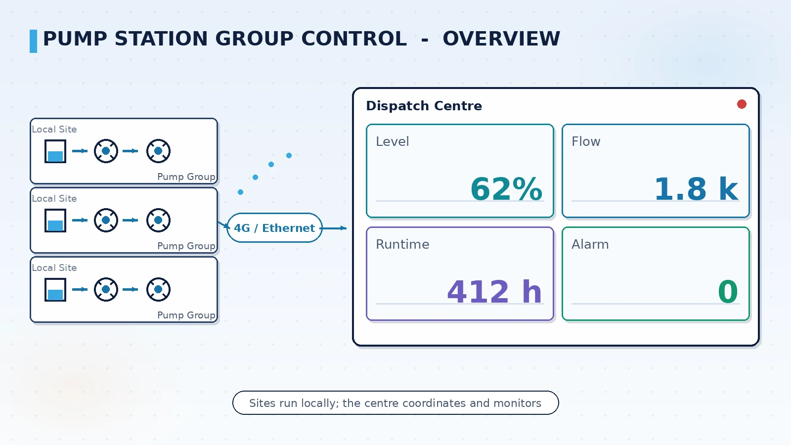
Why pump stations need group control
A single pump station is about moving water out; a group of stations is about scheduling an entire network. One site only needs its local control loops, while a group must also handle load sharing between pumps, level coordination across stations, and staffing during night shifts and flood seasons. Once the number of managed stations grows from one or two to a dozen, station-by-station inspection and manual pump switching run into both cost and safety limits.
- Staffing cost: duty staff scale with the number of sites, and nights and holidays are the tightest
- Dispatch response: storm and peak-demand windows can be as short as tens of minutes, which manual calls cannot cover
- Equipment life: keeping one pump running continuously without rotation pushes the lead pump into maintenance earlier
- Data completeness: without a shared recording convention, fault investigation falls back to shift logbooks
Group control is not just about making every pump automatic; its value comes from a single set of dispatch rules shared by the group, and site-level automation is only the prerequisite.
Three layers: local autonomy, group dispatch, remote supervision
Understanding pump station group control starts with separating what each layer does. The three layers are linked by a communication network, and when any one layer disconnects, the layer below must keep working — this is the point most often missed during selection.
| Layer | Location | Main responsibility | Behaviour when the link is down |
|---|---|---|---|
| Local autonomy | Site panel / PLC | Pump start-stop, level and pressure loops, local protection | Keeps running on local setpoints, data cached locally |
| Group dispatch | District center / HMI server | Inter-station rotation, load sharing, gate and screen linkage | Issued strategy continues, reconciled when the link returns |
| Remote supervision | Cloud / dispatch center | Central monitoring, reports, mobile view and alarm push | Affects monitoring and reports only, not site operation |
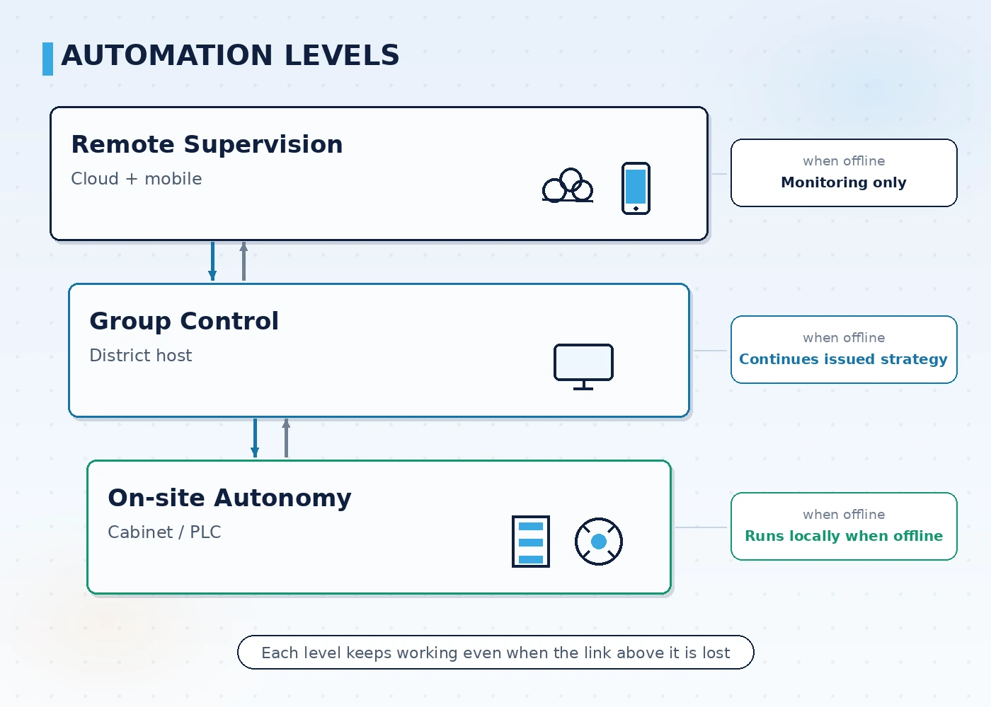
The purpose of this split is that remote supervision handles viewing and dispatching without putting site safety on the network. When the link drops, stations keep running on local setpoints and upload cached data after recovery, so the dispatch system does not become a new single point of failure.
How duty rotation and level control logic are defined
The core of group control is the control logic, and the core of that logic is which pump starts when. A common approach uses level and flow as the primary criteria, combined with accumulated runtime and fault status for rotation, so that load is spread across the pump group.
- Level first: set start, stop and alarm levels to avoid frequent switching that causes water hammer and motor wear
- Balanced rotation: sort by accumulated runtime and start the pump with the shortest runtime first, so pump life converges
- Fault bypass: when a pump reports a fault it is removed from the available set, and the remaining pumps are re-allocated
- Variable speed: use variable-frequency constant-pressure control within the level band to reduce frequent starts of large pumps
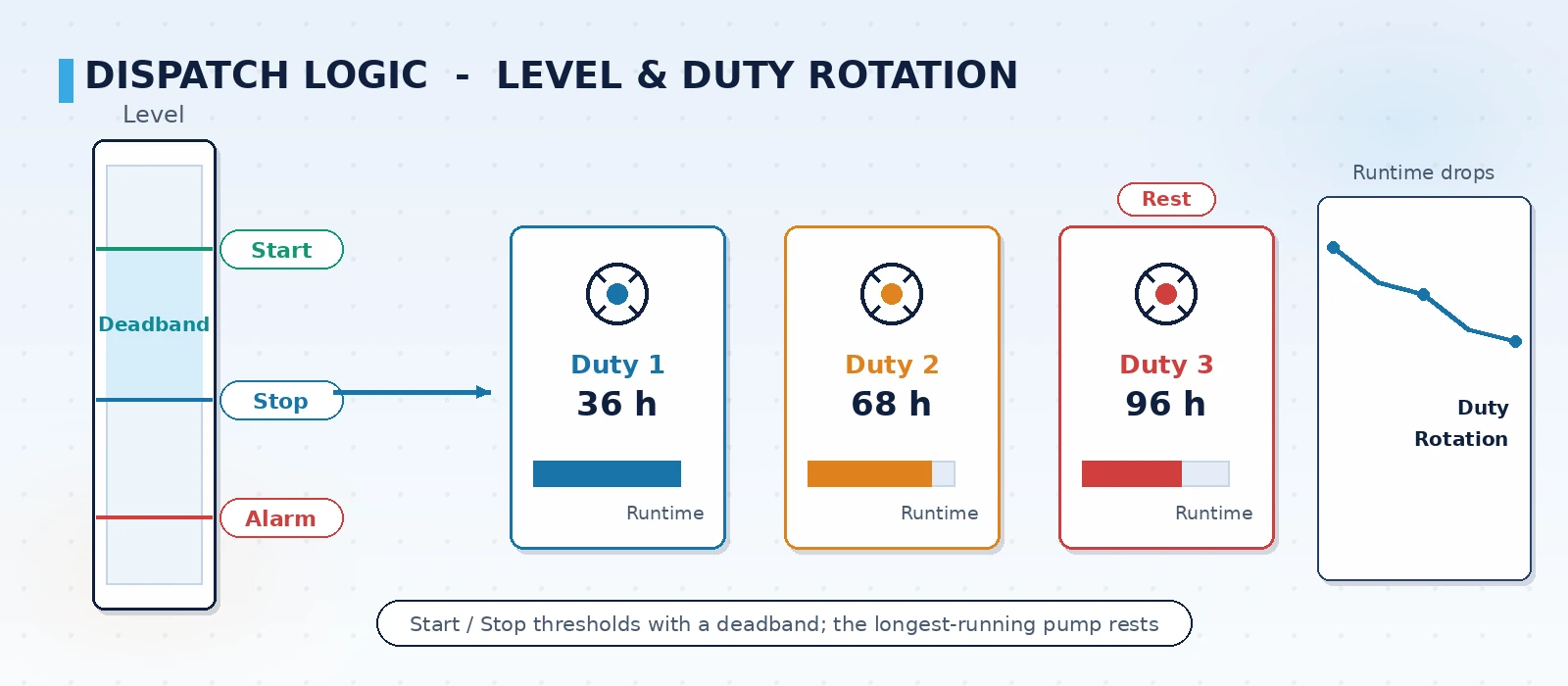
Leave enough differential between start and stop levels, otherwise frequent switching appears when the level fluctuates near the threshold — the most common rework point during pump station commissioning.
What multi-site centralized supervision has to solve
As the number of stations keeps growing, the centralized layer shifts from control to coordination. This layer does not run real-time loops; it compares, dispatches and records across stations.
- Central monitoring: aggregate key parameters from all stations on one screen so duty staff see the whole network at a glance
- Common definitions: compute runtime, energy and fault statistics for every station by the same rules for fair comparison
- Dispatch coordination: during the flood season, coordinate gates and pumps by upstream level and downstream capacity to avoid local flooding
- Record keeping: archive operation logs, alarms and reports by station to support audit and review
How it relates to HMI and SCADA
In engineering practice, pump station group control is usually implemented as HMI software plus SCADA configuration rather than a separate standalone system. The benefit is that instruments, PLCs, video and network devices at each site reuse one set of integration and naming conventions.
- Site template: turn one station's screens, naming and alarm rules into a template and copy it to the next station
- Protocol integration: Modbus TCP/RTU, serial RS485 and 4G uplink are common on site and must be checked station by station
- Video linkage: an alarm triggers the camera view of that station to help duty staff confirm what is happening
- Mobile: alarm push and inspection records through phones reduce night-time site visits
A phased rollout path
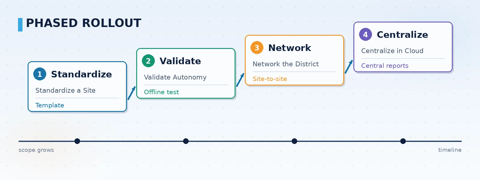
Group control is not a one-shot project; a phased rollout lets you validate while running and limits the impact on normal water supply and drainage.
- Standardize a site: pick one representative station and fix its screens, naming and alarm rules as a template
- Validate autonomy: verify level control and rotation logic at that site, including behaviour when the link is down
- Network the district: connect the stations in a district to one HMI server and verify inter-station rotation and linkage
- Centralize in the cloud: deploy central monitoring and reports, add mobile alarms, and form unified multi-site supervision
ORPAON has developed industrial software and automation systems since 2009, with multiple project practices in pump station and water plant monitoring for municipal water utilities, covering intake, booster, lift, stormwater and wastewater pump stations, and has delivery experience in site templating and multi-site centralized supervision.
Points to verify during selection and acceptance
- Offline behaviour: does the site keep running on local setpoints and cache data when the HMI link is lost
- Rotation logic: does it rotate by accumulated runtime or start count, and can the parameters be adjusted on site
- Interface boundary: list the instruments and PLC protocols to be integrated and confirm each has been adapted
- Alarm tiers: separate equipment faults, level violations and communication loss, and define a notification path for each
- Record completeness: can alarms, operations and reports be exported by station and time to meet audit needs
Conclusion
The value of pump station group control is not in making pumps automatic, but in bringing a group of stations under one set of dispatch and recording rules. Start by standardizing a single site, validate local autonomy and offline behaviour, then extend to district networking and cloud centralization. Keep the three layers independent, with the remote layer handling supervision and dispatch only, so site safety never depends on the network. ORPAON provides scheme design and system development for pump station and water plant monitoring in municipal water utilities and industrial park water plants, supporting site templating and multi-site centralized supervision, with engineers available for direct contact.
Discuss your pump station group control plan
Tell us the number of pump stations, the area you manage and your existing instrument and PLC conditions, and we can outline the group control layering scope and a phased rollout path for your project, with direct access to our engineers.
Contact Us