PLC Program Standardization: Layers, Naming, Versions
PLC program standardization means splitting the control program into device, unit, process and common layers, fixing signal meaning with one naming rule and one tag list, and using version control plus backup restore so that every on-site change can be traced and rolled back. The aim is not elegant code. It is that the same class of machine can reuse the same skeleton across projects, and that whoever takes over does not have to read every ladder rung from the beginning. The sign that it worked is concrete: about seven tenths of the control logic in a new project comes from existing templates, and a new maintainer can locate the faulty section within half a day. This article explains how to cut the layers, how detailed naming and comments should be, and what a handover has to leave behind.
1. What PLC program standardization is: turning personal habit into an engineering asset
PLC program standardization is the act of narrowing how control programs are written, from individual habit into a structure the team can reuse. Two engineers writing the same packaging machine may differ in tag naming, in how sections are divided, and in how alarms are handled. Three years after delivery, when the original developer has left, the person taking over first spends several days reading the logic before daring to change one interlock condition. That is where standardization pays: structure, naming and documentation follow a shared convention, so anyone can walk the same path to the same place.
The boundary needs to be stated clearly. Standardization constrains how the program is organized and what is delivered; it does not constrain the process itself. Recipes, cycle times and motion sequences still follow the customer's process. Reading it as a restriction on coding style is a common misunderstanding: what gets fixed is the skeleton and the interfaces, and the process logic actually becomes easier to change once the layers are clear. IEC 61131-3:2013 already defines program organization units (POUs), function blocks and global variables. The engineering work is to map those concepts onto project folders, section order and naming rules, not to invent a parallel system.
One practical test: hand the program to someone who did not develop it and ask for a single change, such as adding one station. If that person can find the insertion point inside the existing structure without touching the logic of other stations, the program is standardized. If they have to read the whole thing first, standardization stopped at file naming.
2. How to cut the layers: device, unit, process and common
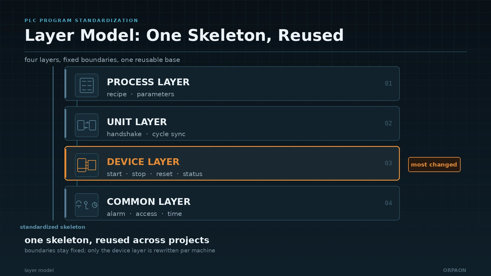
The purpose of layering is to separate logic that changes at different rates. Device-level motion detail changes with mechanical structure, unit-level coordination changes with line layout, process-level recipes change with product, and the common layer of alarms, permissions and communication rarely changes. Mix those four kinds of logic into one block and every change forces you to re-verify everything.
- Device layer: start and stop, interlocks, limit switches and single-machine fault handling. One function block per device, exposing only four interfaces outward: start, stop, reset and status.
- Unit layer: coordination between stations or machines, such as handshakes, cycle synchronisation and buffer decisions. This layer calls device-layer interfaces only and never reads or writes another unit's internal variables.
- Process layer: recipes, parameter sets and process step sequences. Recipe data lives outside the program in a parameter table or database, so changing a recipe does not require a program download.
- Common layer: alarm classes, operator permissions, clock synchronisation, communication mapping and data logging. Shared once across the project instead of rewritten per station.
On the engineering file level, layering becomes a fixed folder structure and section order: each function block starts with an interface description, then the body logic, with exception handling at the end of the section. Once the convention is set, code review gains a shared language: the reviewer first checks whether interfaces cross layers, then whether the logic matches the process.
A caution: more layers is not automatically better. For a project with a single machine type and small batch counts, four layers add maintenance surface. Keeping device and common layers and writing coordination at the call site is more practical there. Layer granularity should follow equipment repetition, not a template.
3. Naming, tag lists and comments: making it readable for the next person
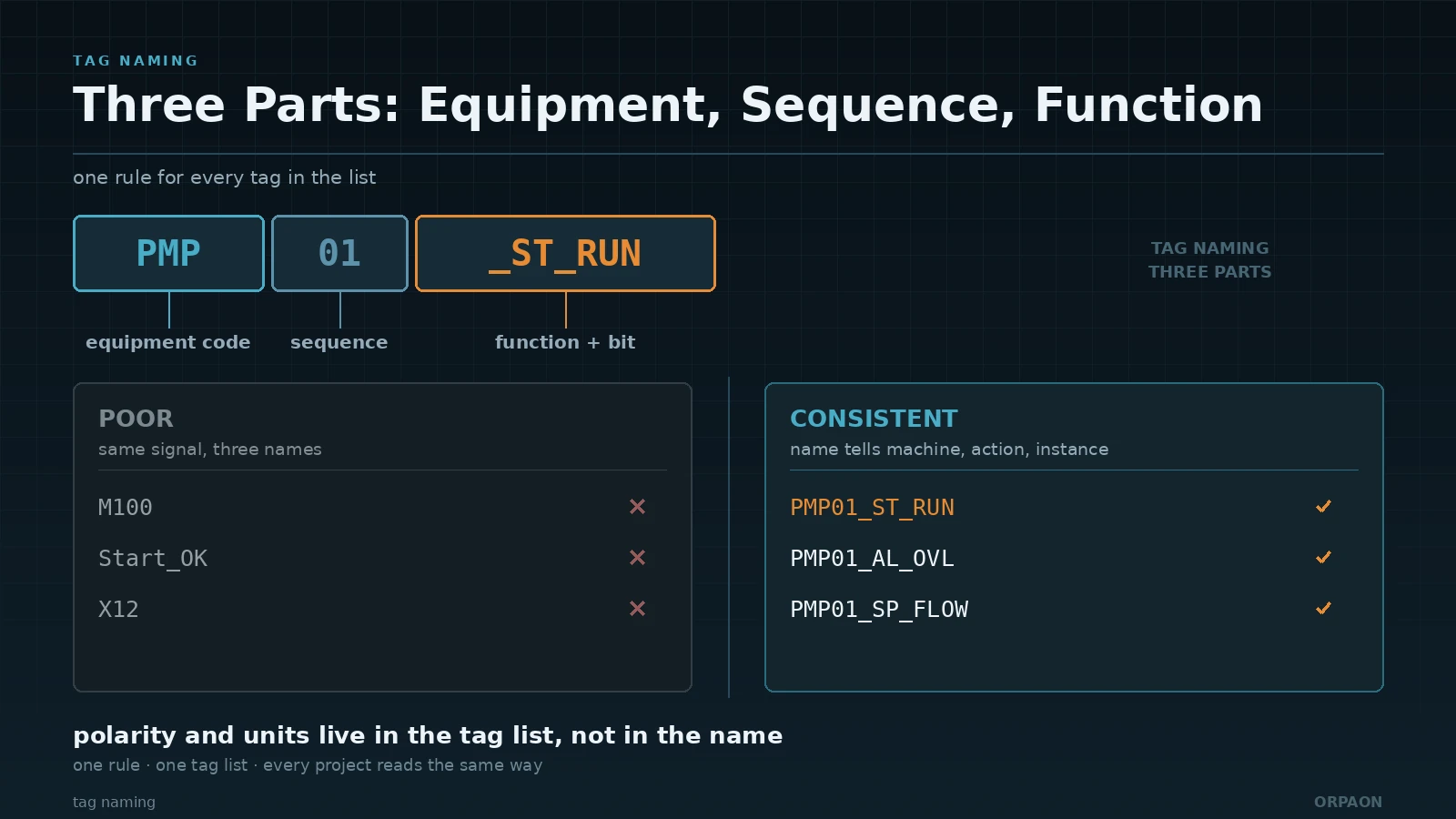
Naming has the highest return on effort in the whole standardization effort. When the same signal is called M100 in one project, Start_OK in another and X12 in a third, maintenance becomes guesswork. A three-part name fixes equipment, function and sequence, so the name itself says which machine it belongs to, what it does and which instance it is.
| Item | Convention | Common problem |
|---|---|---|
| Equipment code | Abbreviate by process section: FIL for filtration, PMP for pump, CVY for conveyor; the code table ships with the project | The same device is written differently per station, so nothing carries across projects |
| Function code | IN input, OUT output, AL alarm, ST status, SP setpoint, PV process value | Status bits and alarm bits are mixed, so a reset overwrites the other |
| Sequence and bit | Two-digit sequence plus internal bit, for example PMP01_ST_RUN | Sequences skip numbers or get reused, so old drawings no longer match |
| Logic polarity | Normally open or closed and positive or negative logic is noted in the tag list, not encoded in the name | Field staff judge on or off from the name and misread the fault point |
| Comment depth | Each function block states its purpose and call condition; key interlocks state the consequence of violation | Comments say "start" but not what it interlocks with or what stops when violated |
The tag list ships with the program, not as an afterthought. At minimum it carries address, data type, range and engineering unit, owning function block, initial value and retentive flag. Analogue signals deserve extra care: if the 4–20 mA to engineering range mapping, the filter time and the wire-break threshold are not written down, the next person to tune it will drift it.
How far should comments go? A workable test is to read the comment on its own: without looking at the code, can you say under what condition this block is called and what happens if it fails? If not, the comment is describing an action name rather than a design intent.
4. Version control, backup and handover acceptance
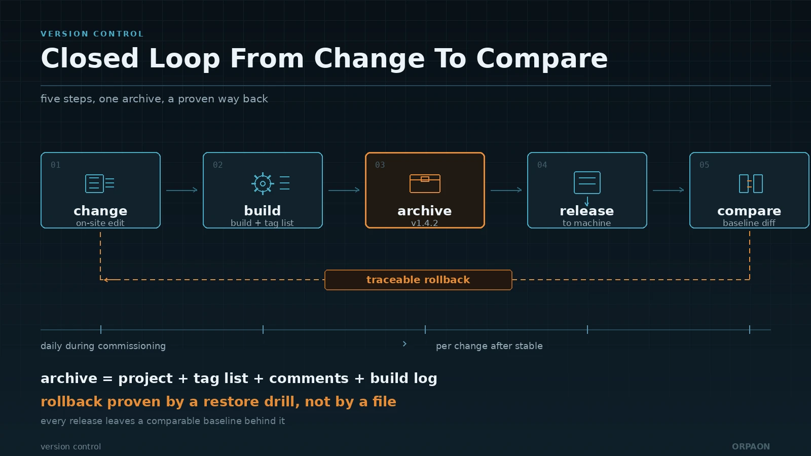
On-site change is the main source of program drift. A dozen revisions a day during commissioning is normal; without a version record, a week later nobody can say which revision runs on the machine and which was experimental. Version control has to answer three questions: which revision is running, what changed in it, and which revision to fall back to.
- Version numbering: a major number for process or structural change, a minor number for parameters and local logic; the version appears both in the first comment block of the program and on the label inside the cabinet, and the two must agree.
- Archiving rhythm: archive daily during commissioning, then on every change once stable; an archive holds the source project, tag list, comment notes and build log, and a missing item breaks the chain for the next person.
- Change record: note who changed what, when, why and with what impact; changes to interlocks and safety-related logic are flagged separately and reviewed.
- Backup and restore: keep one offline-restorable backup at the machine and one historical set on the server; the validity of a backup is proven by a restore drill, not by the file existing.
Safety-related logic carries additional requirements. ISO 13849-1:2023 sets out a design and verification path for safety-related parts of control systems, and a safety function cannot simply live in an ordinary program section distinguished by a comment. EU Machinery Regulation (EU) 2023/1230 applies from 20 January 2027, and software acting as a safety-related part needs a traceable version and verification record. IEC 62443-3-3:2013 requires control over program modification and access: who may download, who may change parameters, and whether changes are logged belong in the delivery scope, not in the optional extras.
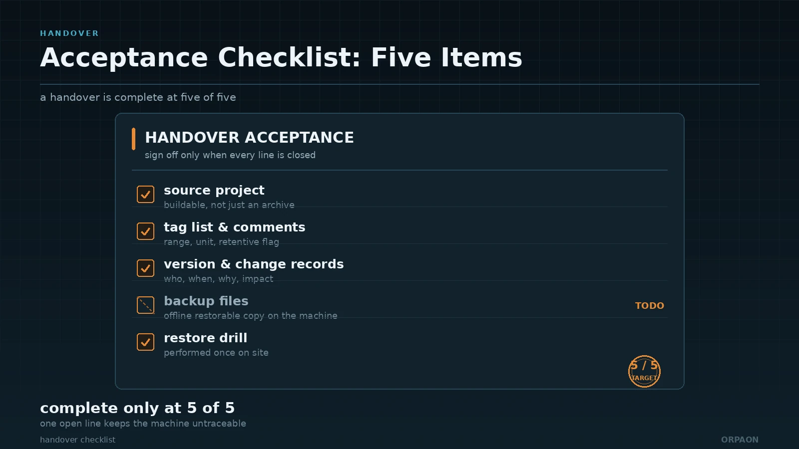
Handover acceptance is best done as a checklist, complete only when all five items are present: the source project and a buildable project, the tag list and comments, version and change records, backup files with restore steps, and one on-site restore drill. The drill is the step most often skipped and the one that exposes the most: a backup file that exists but cannot be restored is not uncommon.
Conclusion: standardization saves the cost of taking over
The return on PLC program standardization rarely appears on an acceptance form. It appears three years after delivery, during a fault: whether the person taking over can locate the faulty section within half a day, whether changing one interlock disturbs other stations, and how long a rollback takes. Layering, naming and version control all do the same thing — they turn a program from personal experience into a team asset. For a machine builder the direct result is higher reuse in new projects and a shorter commissioning cycle; for a plant it means maintenance is no longer tied to the original developer. A sensible start is one high-repetition machine model, proving the skeleton there before copying it to others, which lands more reliably than a plant-wide rollout in one step.
Book a solution discussion
If you are moving toward PLC program standardization, or want to review the naming rules, version management and handover checklist of your existing programs first, contact us to discuss equipment types, reuse scenarios and delivery requirements. We will suggest a staged path based on how repetitive your machine models are and what state the current programs are in.
Contact Us