What an FMCS Facility Monitoring System Covers
An FMCS (facility monitoring and control system) connects dispersed utility subsystems such as cleanroom environment, compressed air stations, process gas, exhaust and wastewater and facility energy metering into a single acquisition and monitoring platform. The value is not the screen itself, but the fact that facility teams stop switching between separate vendor software packages, read the whole plant on one console, alarm under one rule set and answer audits with one record.
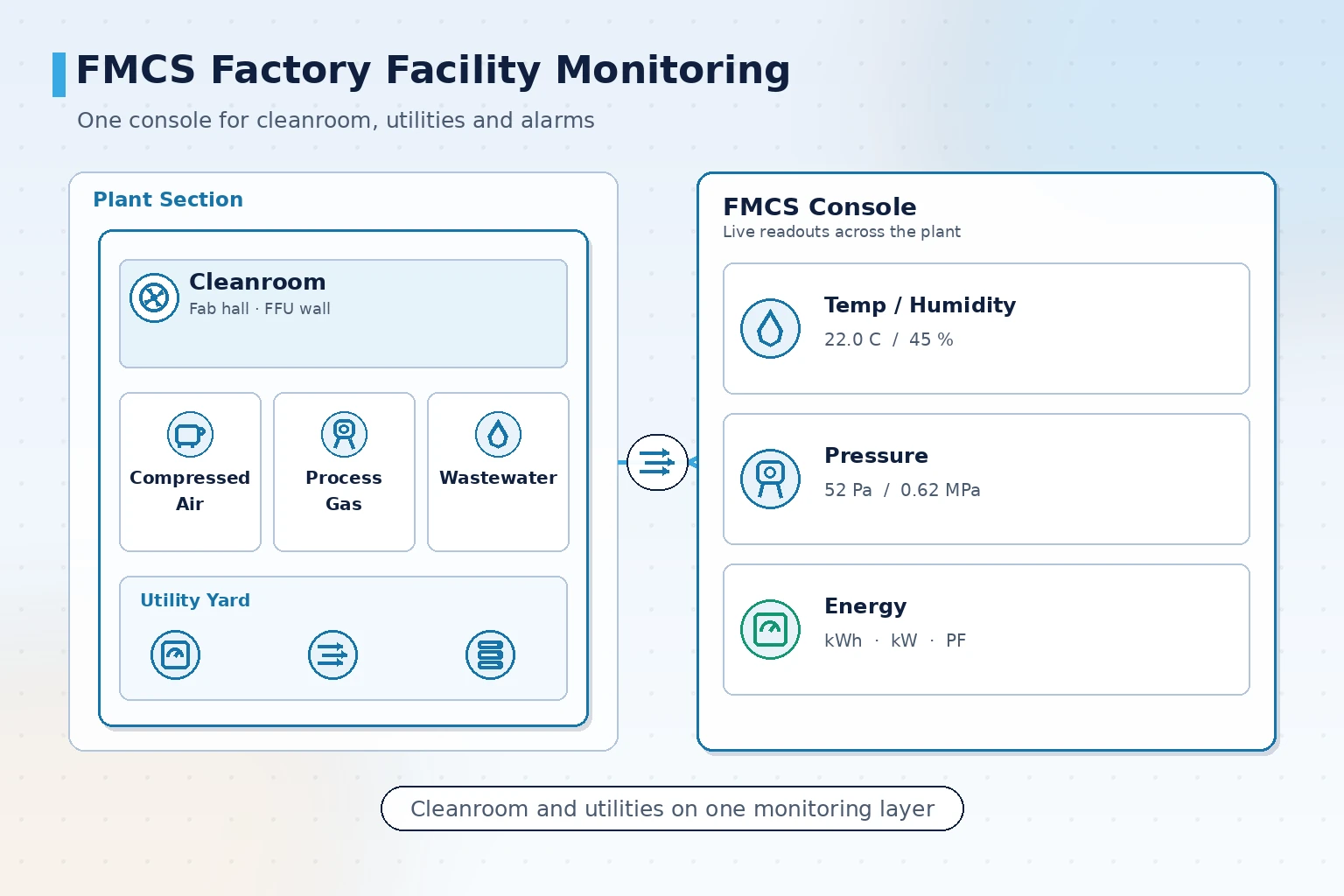
How FMCS differs from monitoring each subsystem separately
The most common detour in facility monitoring is buying a separate monitoring package for each subsystem: one for the cleanroom, one for the compressed air station, another for the wastewater plant. Data is rarely missing on site; what is missing is a mechanism that puts the data side by side.
FMCS starts by defining a unified acquisition layer, then builds judgement and visualisation on top of it. Subsystem differences are absorbed at the acquisition layer, so the operator sees one console.
- Unified acquisition layer: air handling units, temperature and humidity sensors, power meters and gas detectors connected over BACnet, Modbus TCP/RTU and OPC UA
- Unified judgement layer: alarm rules, priorities and suppression logic configured in one place rather than duplicated inside each subsystem
- Unified visualisation layer: control-room video wall, desktop client and mobile views share the same live data
- Unified record layer: environmental parameters, alarm events and handling records sit on one timeline for later traceability
A practical test: if confirming a single environmental deviation means opening three software packages, the facility monitoring system is not really in place yet.
Which points does cleanroom environment monitoring need
Cleanrooms are the part of a facility that cannot be managed by feel. The effect of environmental drift on yield tends to appear with a delay, and by the time finished-goods inspection flags a problem the window to act has closed.
| Monitored object | Typical parameters | Common response | Priority |
|---|---|---|---|
| Clean zone rooms | Temperature, relative humidity, differential pressure | Alarm on limit breach and adjust the AHU | High |
| Air handling units | Supply air temperature, fan status, valve position | Abnormality raises a maintenance work order | High |
| Process gas rooms | Gas concentration, cylinder pressure, exhaust status | Tiered alarm with on-site dispatch | High |
| Exhaust and wastewater | Flow, pH, equipment running status | Record on limit breach and retain for audit | Medium |
| Utility energy | Sub-metered electricity, compressed air and water | Specific-consumption comparison and abnormal-use localisation | Medium |
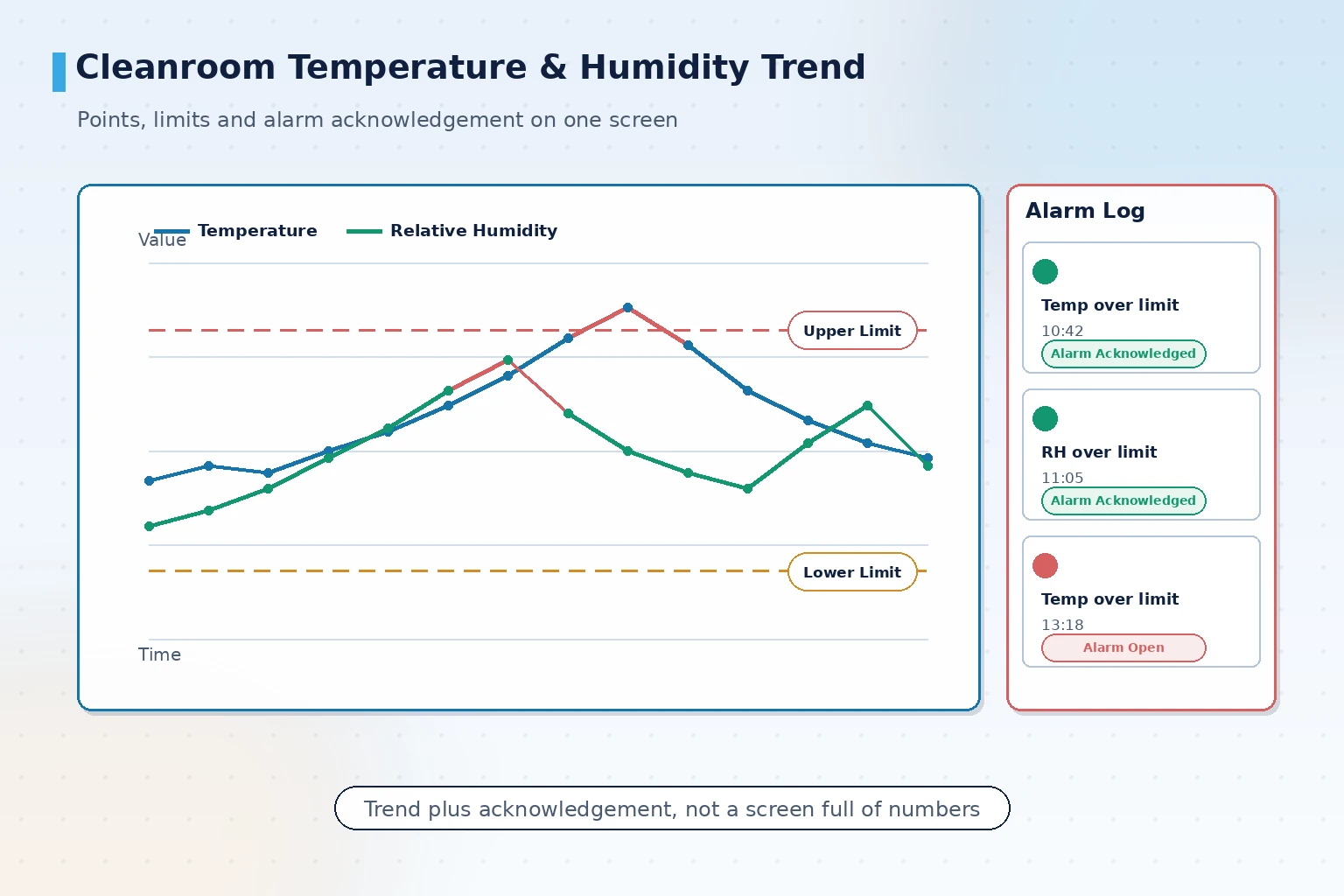
Temperature and humidity point density should be graded by zone importance rather than spread evenly. Dense coverage at yield-sensitive stations, room-level coverage in auxiliary areas, is usually sufficient.
Alarm tiers and response: avoiding alarm fatigue
If every facility alarm uses the same audible and visual signal, operators begin ignoring them within about three months. Tiering only matters when each level maps to a different action.
- Advisory level: parameter approaching the threshold, tile turns amber, log only, confirmed by the inspection round within the shift
- Alarm level: outside the process tolerance, audible and visual alert pushed to the shift owner with a time-limited response
- Emergency level: safety and compliance events such as special gas leaks or wastewater exceedance, triggering the on-site response procedure directly
Suppression and delay belong to tier design as well. A temperature and humidity disturbance during an AHU changeover, if alarmed unconditionally, will keep generating pointless site visits.
Alarm tiers must be bound to response timing and handling records, otherwise tiering is just a label. The system logs the trigger time, responding person, action taken and closure time of every alarm so the event can be explained afterwards.
Integrating utility subsystems onto one platform
For integration order, proceed by "safety and compliance first, energy second, comfort last" rather than by subsystem launch date.
- Safety and compliance first: process gas room monitoring and exhaust and wastewater monitoring, where loss of control directly triggers an incident or an audit finding
- Then production-critical utilities: compressed air station group control, air handling units and chilled water plant monitoring, where loss of supply stops the line
- Then energy metering: power meter acquisition and compressed air metering, which form the basis for specific-consumption analysis
- Finally comfort and auxiliary areas: general ventilation and lighting zones
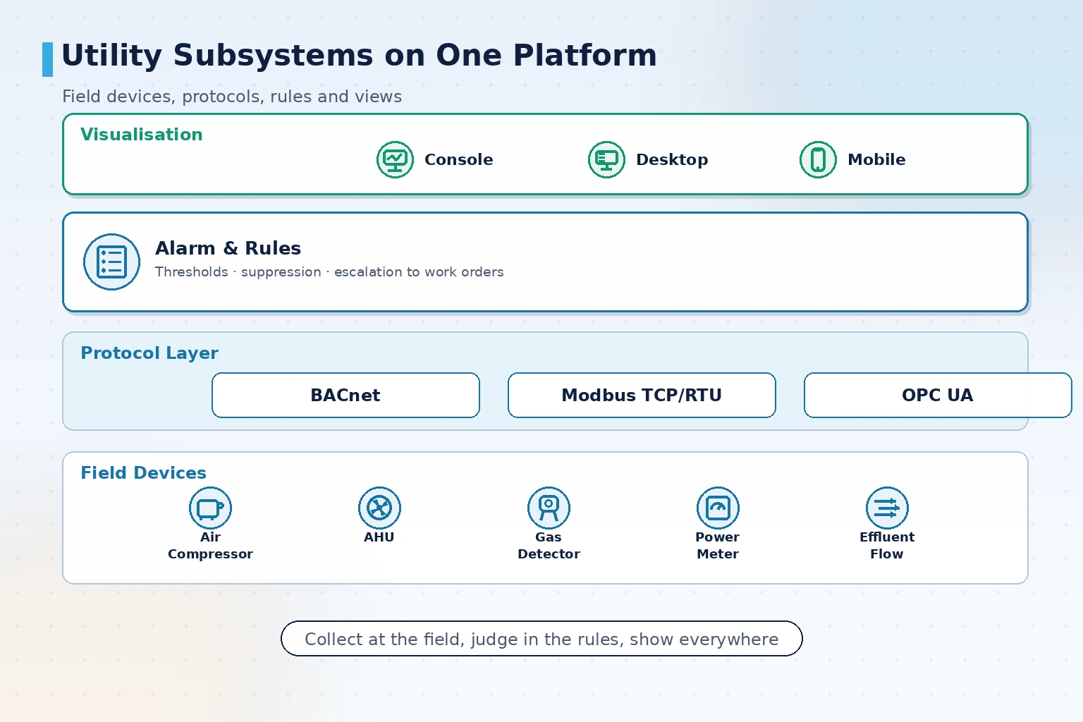
The most under-estimated part of integration is protocol work. Air handling unit controllers, gas detectors and power meters from different vendors differ in implementation detail, so each point list must be verified at the acquisition layer. Assuming that 'everything speaks Modbus' is not enough to connect.
Delivery boundaries and acceptance: what to settle before starting
The acceptance difficulty of facility monitoring is that it naturally spans several trade packages. Without boundaries set in advance, arguments over 'whose point is this' appear after delivery.
An acceptance checklist should include:
- Point list verified item by item: actual acquired values compared with field instrument readings, range and unit confirmed
- Alarm rules tested: each rule triggered once, with level, recipient and record content confirmed against the agreement
- Historical data completeness: acquisition rate, retention period and backfill after disconnection meeting audit retention requirements
- Report format confirmed: fields and periodicity of audit-ready reports aligned with facility and audit departments in advance
- Permissions and traceability: user levels, operation logs and modification records traceable
Delivery status normally has three tiers: already delivered (in operation on site), deliverable (solution and references ready for immediate start) and customisable pilot (validated against site conditions). For multi-subsystem facility integration, run a pilot on one building or one subsystem, verify the acquisition layer and alarm rules, then roll out across the plant.
How mobile inspection dispatch connects to the equipment register
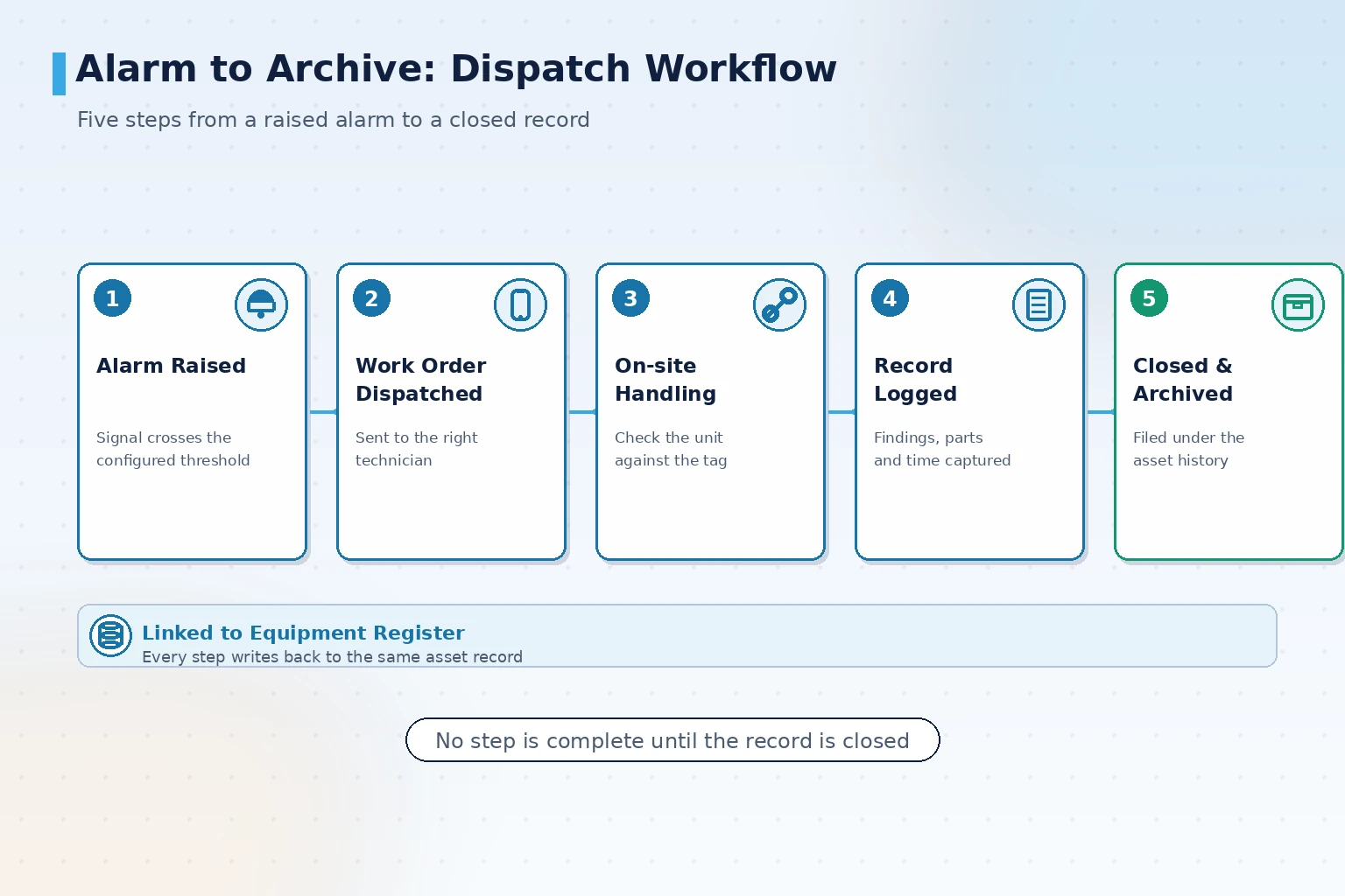
Centralised monitoring answers "can we see it"; inspection dispatch answers "will someone go". When the two drift apart, alarms sit unattended or inspection records contradict alarm records.
Connecting inspection dispatch to the same platform requires alignment in three places: dispatch source aligned with alarm records, handling actions aligned with the equipment register, and completion status aligned with closure time. That gives equipment register and maintenance work a factual basis instead of a paper trail filled in after the fact.
In multi-site scenarios the solution template can be replicated to a new plant: standardise the acquisition point list by equipment type and deploy it as the new plant is built, avoiding a fresh design exercise for every building.
Where facility monitoring lands: from scattered duty desks to one console
An FMCS facility monitoring system answers three questions rather than one: how many software packages the facility data is scattered across, how quickly an abnormality is found, and whether a traceable record can be produced afterwards. Integrate subsystems in the order of safety and compliance, production assurance and energy metering; bind alarm tiers to response timing; verify the point list and alarm rules item by item at acceptance. Get those three right and the facility team genuinely moves from walking the plant to reading the console.
Request an on-site diagnosis
If your plant is dealing with subsystems that operate in isolation, or environmental and energy data that will not reconcile, submit your site information and we will propose an integration path based on your existing subsystems and point conditions.
Contact Us