Factory Digital Twin System: Model Fidelity and Data Path
A factory digital twin system puts a 3D view of shop-floor equipment and live state data on the same screen: what you see is not just a diagram, but whether a machine is running, stopped or alarming right now. Its first job is to answer "equipment is spread across several workshops and systems, and I cannot see the whole picture", not to make every model photo-real. Getting a digital twin to work comes down to three things: setting model fidelity at the level the questions actually need, wiring state data to the model reliably, and getting the shift to actually use it every day. This article covers model fidelity tiers, the data-driven approach, the data path from PLCs to the 3D scene with its latency budget, typical use cases and boundaries, performance constraints, and a staged rollout with acceptance points.
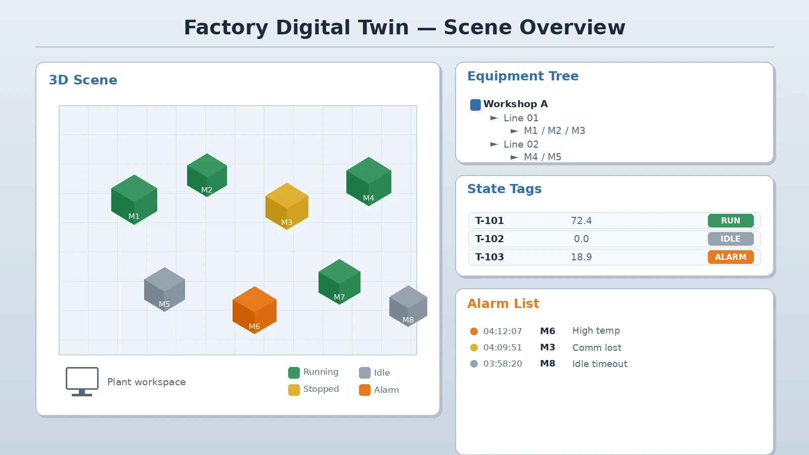
The three questions a digital twin answers
A digital twin's value is not how good the model looks; it is turning "what state is this machine in right now" into something visible at a glance and traceable back to a specific station. Define the questions first, so the model fidelity and data fields have a basis.
- Is this machine running, idle, stopped or alarming, and what is its current cycle time and output
- Which machine and which process does an alarm come from, and does it affect the adjacent process
- What is the current capacity load of the workshop, and which machines are the bottleneck
- Are these states consistent when broken down by workshop, line, machine and shift
- Do the states on the model match the shop floor, and where does any deviation come from
A common mistake is making the model very detailed first and only then asking how data connects. The more reliable order is the reverse: decide which states you need to see and which points the data comes from, then decide how detailed the model should be.
Fidelity boundaries and modelling strategy
Not every digital twin needs part-level detail. Model fidelity must match the questions being asked, because higher fidelity grows the modelling workload, the runtime cost and the maintenance burden.
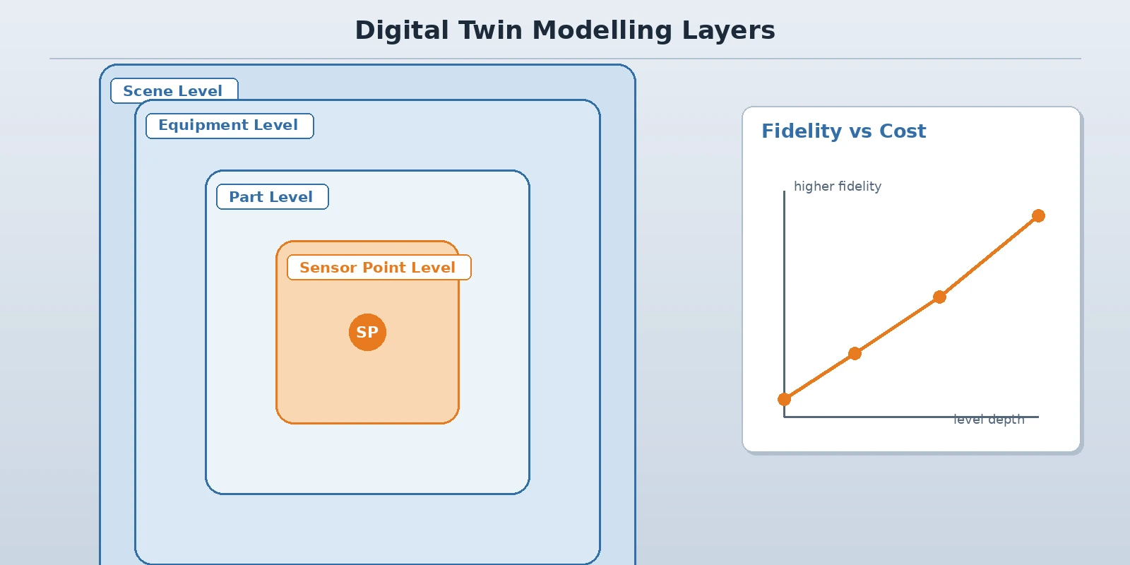
- Scene level: the plant or workshop shell, line layout and equipment positions, for overview and site visits
- Equipment level: the shape and main moving parts of a single machine, for reading operating state and process handover
- Part level: the moving parts of key mechanisms, for showing cycle motion and station-level state
- Sensor point level: state points, gauge readings and alarm markers attached to the model
- Fidelity trade-off: limit it to what supports a decision; texture and decoration can be simplified heavily
Modelling route and data-driven behaviour
Settle the modelling route early, because it decides whether the model can be changed later and how long a change takes. Also separate what the model carries statically from what live data drives, so a static drawing is never mistaken for live state.
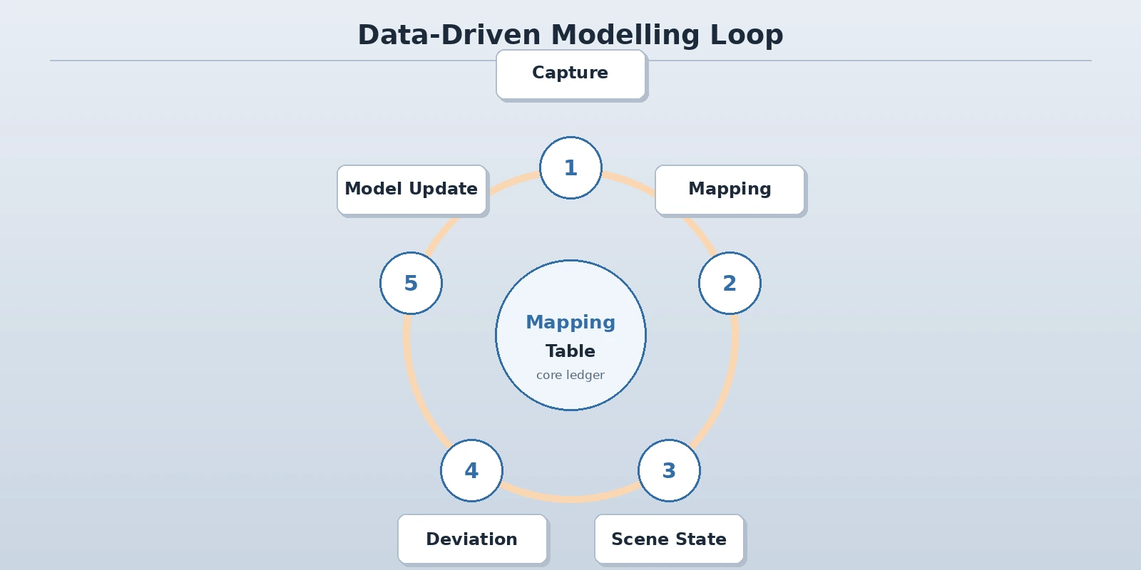
- 3D modelling: build scene and equipment models from drawings, point clouds or site surveys, keeping proportion to the real dimensions
- Lightweighting: reduce and merge internal structure that does not affect judgement, controlling polygon count and texture size
- Data driving: a machine's colour, position, animation and label are driven by live data; static appearance is built once
- Mapping table: maintain the equipment-number to model-node to data-point relationship, the core ledger for later maintenance
- State rules: agree what colour and behaviour represent running, idle, stopped and alarm, and keep it consistent plant-wide
- Deviation comparison: measured data can be compared against model-calculated values to find states that do not match
Data path: from PLC to 3D scene
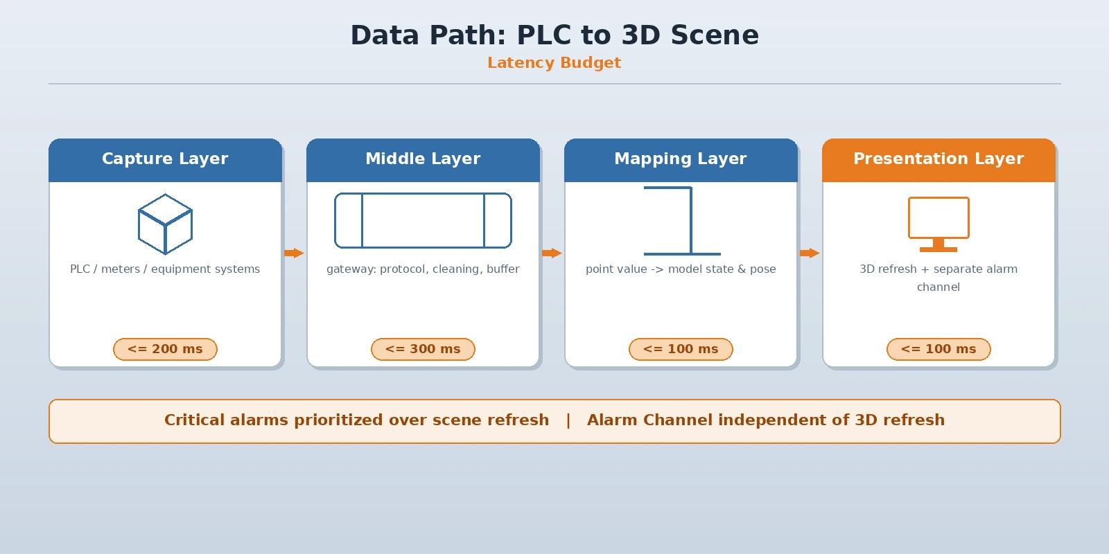
Refreshing the 3D scene depends on a stable data path. Separate periodic polling, change reporting and event-triggered data, and give each segment a latency budget, or the picture looks good but is not accurate.
- Capture layer: read state, counts, process parameters and alarms from PLCs, instruments and equipment systems
- Middle layer: a gateway or capture service handles protocol conversion, data cleaning and buffered backfill, so a network break does not lose data
- Mapping layer: use the mapping table to convert point values into model state and position, handling ranges and units
- Presentation layer: the 3D scene updates colour, animation and labels by refresh policy; alarms use a separate notification path
- Latency budget: set an upper bound per stage from capture to transport to processing to rendering, and let critical alarms take priority over scene refresh
| Data class | Typical interval | Suggested handling |
|---|---|---|
| Running state and counts | Seconds to minutes | Change reporting, refresh the scene on demand |
| Process parameters and trends | Seconds | Periodic sampling, alert on out-of-range |
| Alarms and events | Immediate | Event-triggered, separate notification path |
Typical use cases and boundaries
A digital twin suits problems where state is scattered and hard to see or explain, but it does not replace control logic or act as a single data source. Clear scope is what makes the investment pay back.
- Central monitoring: aggregate equipment state from multiple workshops and lines into one 3D view, replacing scattered supervisory screens
- Alarm locating: jump straight to the machine and process on an alarm, cutting diagnosis time
- Site visits and reporting: use real state rather than a static demo for visits, so no extra preparation is needed
- Maintenance coordination: maintenance and patrol find the machine and adjacent process by position on the model, making handover more direct
- Data asset: build equipment state and position relationships into a visual asset for later analysis and simulation
- Boundary: control logic stays in the existing PLC and control layer; the twin reads state and does not write to the control loop
Boundaries of virtual commissioning and simulation
Virtual commissioning and simulation validation are frequently mentioned digital twin uses, but they demand far more model fidelity, timing and interface work than monitoring, so they belong in a separate stage.
- Higher fidelity: simulation needs accurate motion timing and cycle sequence, which an appearance-only model cannot support
- Timing and interface: it must connect to a PLC or a simulated control environment, with interfaces and timing defined separately
- What to validate: verify logic and timing first, then cycle and handover; do not use a monitoring model directly as a simulation model
- Stepwise approach: first make the data path and mapping table solid in a monitoring case, then assess whether to move into simulation validation
Virtual commissioning and digital line simulation are currently treated as in progress; joint validation can be arranged around a specific line and site conditions, and they are not stated as delivered capability.
Performance and implementation constraints
A 3D scene is sensitive to endpoint performance, so confirm the viewing devices and network conditions up front, or you get "smooth in the demo, laggy on site".
- Endpoint conditions: large screens, workstations and mobile devices differ, so resolution and model fidelity need separate settings
- Polygons and textures: control total scene polygon count and texture size to avoid slowing refresh with excessive detail
- Network and deployment: on-site network and central deployment affect loading speed; use local caching where needed
- Concurrency and permissions: define a concurrency policy when many terminals open at once, and separate operate from view permissions
- Data growth: historical state and alarm records keep growing, so a retention policy must be agreed in advance
- Maintainability: agree who maintains the model and mapping table and how often they are updated, at the implementation stage
Staged rollout
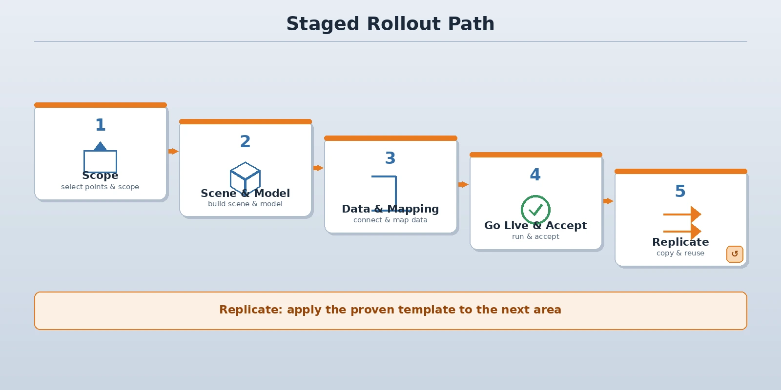
A digital twin should not cover the whole plant at once. Start with one workshop or one line, get the model, mapping table and refresh policy working, then replicate to the next area for the lowest rework cost.
- Scope and select: pick a workshop or line with concentrated equipment and the most pressing visibility problem, and define the questions
- Build scene and model: build the 3D scene and equipment models at the agreed fidelity tier, and prepare the mapping table at the same time
- Wire data and tune mapping: connect the capture path, map point values to model nodes, and verify state machine by machine
- Go live and accept: get monitoring, maintenance and visits actually using it, and work through the acceptance list item by item
- Replicate and accumulate: reuse the model, mapping table and refresh policy in the next area and build a reusable asset
Conclusion
The hard part of a digital twin is not how detailed the model is, but whether its fidelity matches the questions, whether the data path is stable and whether the mapping table can be maintained. Start with the workshop or line where state is most scattered: define the fidelity tier and mapping table, connect the data path, agree refresh and latency budgets, get the shift actually monitoring and responding to alarms with it, and replicate to the next area once proven. When selecting, check five points: matching fidelity, maintainable mapping, a stable path, controllable latency and clear permissions, so the system does not become a display nobody uses. ORPAON has developed industrial software and automation systems since 2009, with project experience in shop-floor data acquisition, production visualization and supervisory monitoring. It delivered a production visualization wall for an aluminium processing plant in Chongqing for central monitoring of shop-floor status, in operation since it went live in 2020. It provides design and development of digital twin and 3D visualization solutions for automotive parts, electronics manufacturing, machining and process industries, supports integration with PLC, SCADA and MES, and offers direct engineer contact.
Talk to us about a digital twin plan
Tell us your workshop layout, equipment types and how you view state today, and we can propose a model fidelity recommendation, a data path design and a staged rollout based on your site conditions, with engineers available for direct contact.
Book a solution discussion
Tell us your workshop layout, equipment types and how you view state today, and we can propose a model fidelity recommendation, a data path design and a staged rollout based on your site conditions, with engineers available for direct contact.
Contact Us