How to architect a data acquisition gateway in five layers
A data acquisition gateway is usually organized in five layers: a signal intake layer reads raw data from machines and instruments, a protocol adaptation layer turns different protocols into one internal tag model, a data cleaning layer handles unit conversion and outlier rejection, a buffering layer keeps data locally during network outages, and a forwarding layer delivers the prepared data to MES, energy platforms or the cloud. Settling these five responsibilities at design time noticeably reduces the rework caused by repeated protocol changes and mismatched numbers later on.
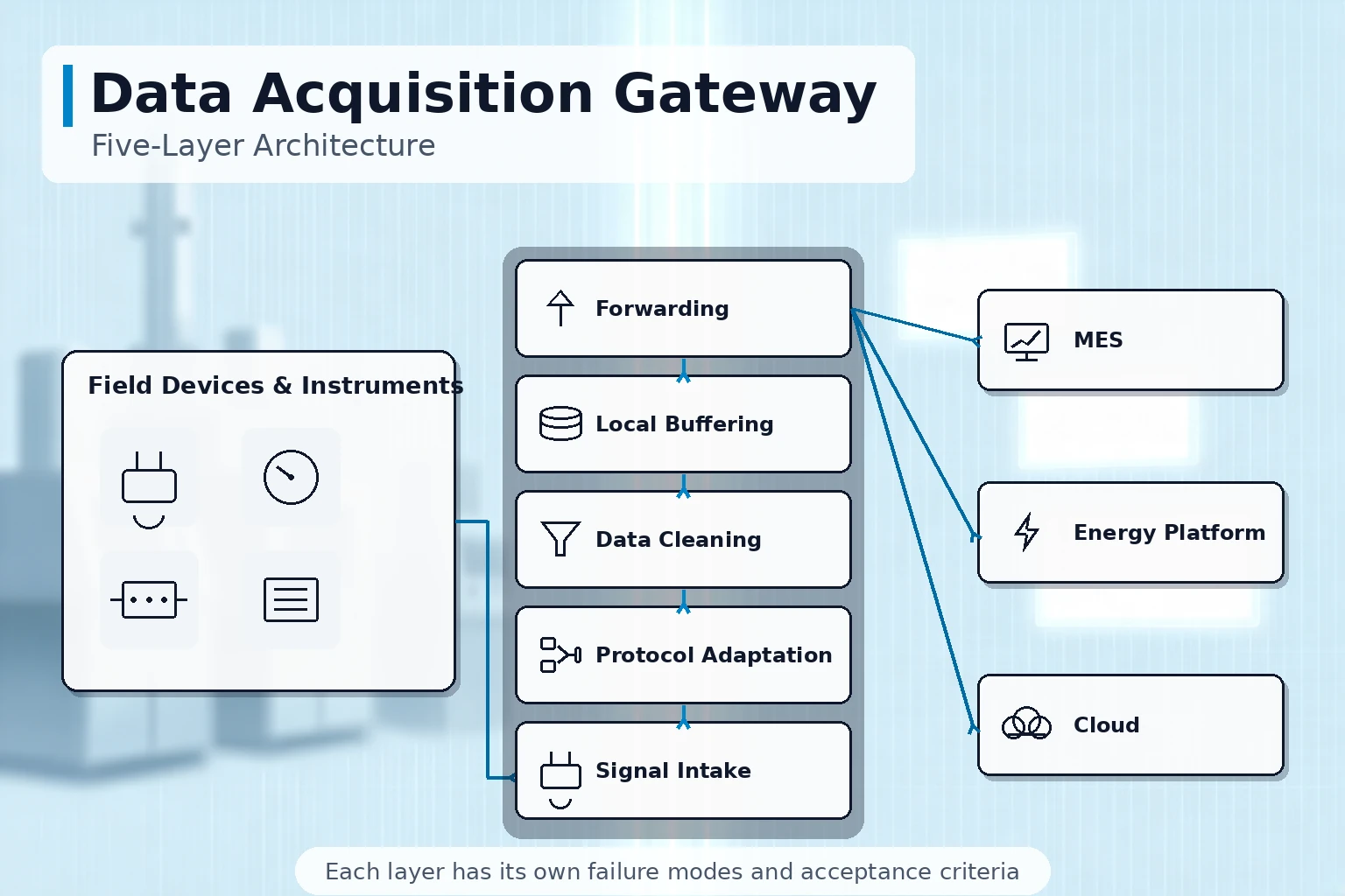
Why shop-floor data is hard to collect
A single workshop often runs several generations of equipment at once: newer machines have Ethernet ports and open protocols, older ones offer only serial links, and the oldest expose nothing but hardwired signals. Their data formats, update cycles and tag naming all differ, so any reporting tool placed directly on top produces numbers that do not agree with each other.
- Newer machines: Ethernet with OPC UA or a vendor-proprietary protocol; complete data, but access rights must be confirmed machine by machine
- Older machines: serial Modbus or RS485 buses; collectable, but register addresses have to be verified one by one
- The oldest machines: only relays and transmitters, which need added I/O modules before they produce data at all
- Field instruments: power meters, water meters and flow meters each carry their own communication rules and are the items most often left out of the plan
The job of a data acquisition gateway is to bring these sources into one pipeline and turn them into data that upper-level systems can use directly.
What each of the five layers does
In engineering practice the gateway is reviewed layer by layer, because each layer has its own failure patterns and acceptance criteria.
| Layer | What it is responsible for | Where problems usually appear |
|---|---|---|
| Signal intake | Physical connections and polling schedules across serial ports, Ethernet and I/O modules | Wiring errors, address conflicts, overloaded polling cycles |
| Protocol adaptation | Converting Modbus, OPC UA, S7, MC and other frames into one internal tag model | Wrong register mapping, inconsistent byte order |
| Data cleaning | Unit conversion, range scaling, outlier rejection, standardized tag naming | Wrong scaling factors, spikes left untreated |
| Buffering | Keeping data on site during outages and resending it in order after recovery | Disk full, out-of-order backfill |
| Forwarding | Pushing to MES, energy platforms and the cloud, and keeping a two-way command path | Upstream interface changes not tracked, duplicate pushes |
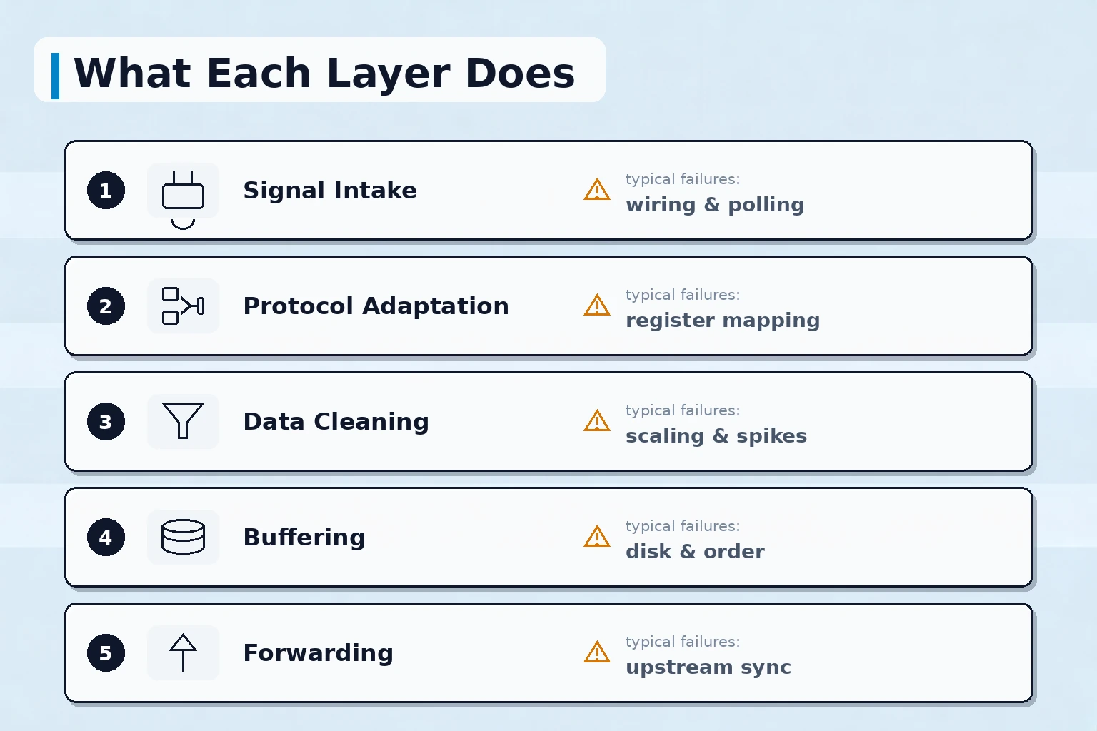
With the five layers separated, the three common complaints — "cannot collect", "numbers are wrong", "data lost during outages" — can each be traced to a specific layer instead of triggering a blanket redo.
The protocol adaptation layer: many frames, one tag model
Protocol adaptation is the layer with the heaviest workload. The workable approach is not to rewrite the program for every new protocol, but to decouple collection from consumption: the adaptation layer converts all frames into one internal tag model, and everything above it deals only with tags, never with protocols.
- Modbus RTU/TCP: register every point from the register map, stating data type, byte order and scaling factor
- OPC UA: published in 2008 and later standardized as IEC 62541; once a device opens its address space, nodes can be browsed and subscribed directly
- Siemens S7 and Mitsubishi MC: register by PLC station and device address, and watch the polling rhythm when several devices share one line
- Vendor-proprietary protocols: parse frame by frame from samples, with the parsing rules held in configuration rather than hard-coded
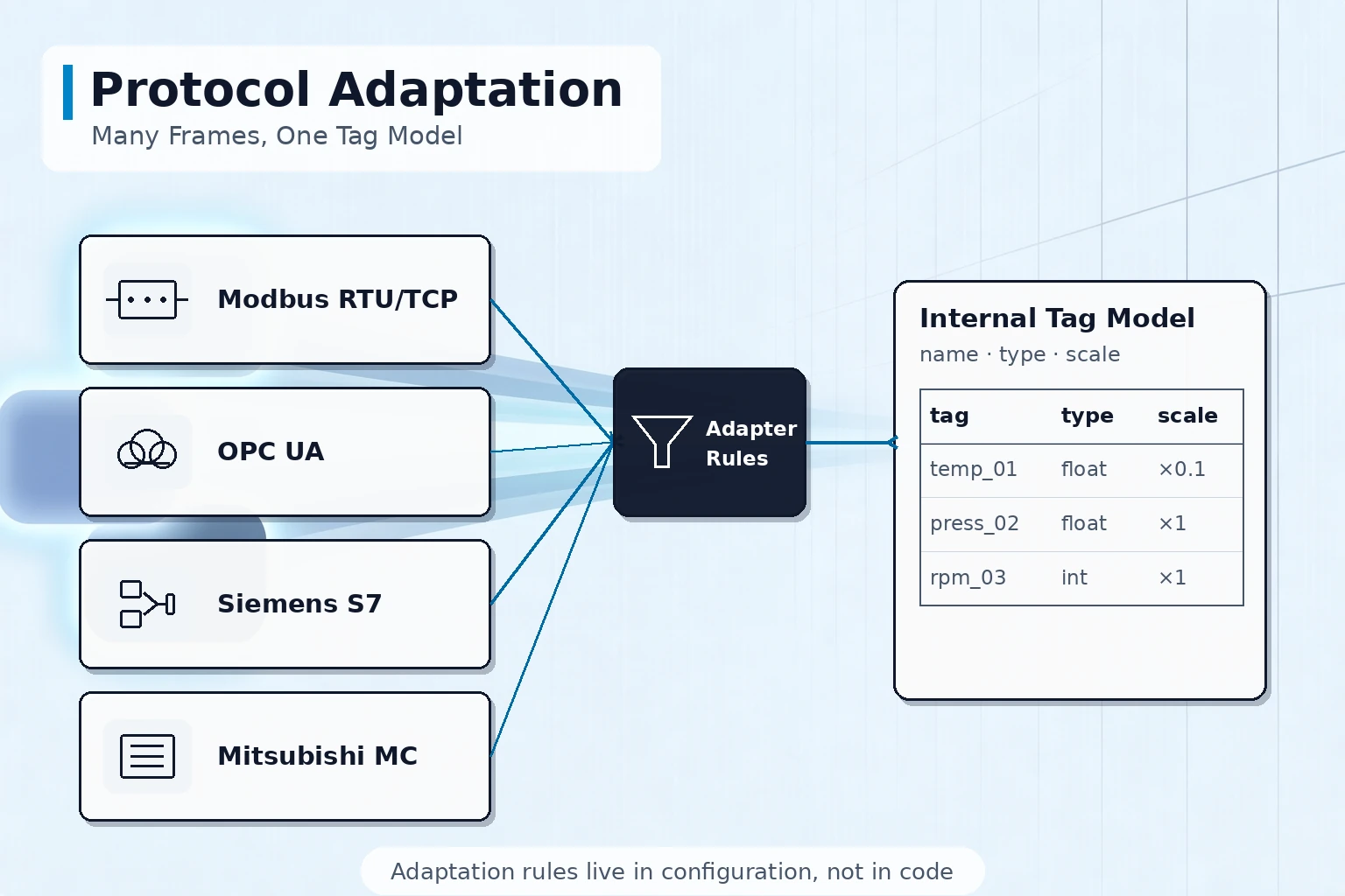
Once adaptation rules live in configuration, adding another identical machine means copying a configuration and changing an address; if the rules are scattered through the code, every expansion becomes a development task.
Where the data goes when the network drops
The link between workshop and server room will not stay up all year: switch reboots, cable work and wireless fluctuations all cause short interruptions. The buffering layer decides whether the data from those periods is lost or recovered.
- Recent data first enters a memory queue, so backfill starts the moment the link returns without waiting on disk writes
- Data beyond memory capacity moves to a disk queue indexed by time and resent in order after recovery
- The buffer carries a capacity limit and a discard-oldest policy so a long outage cannot fill the disk
- After backfill completes, a break marker is recorded so reviewers can tell backfilled data from live data
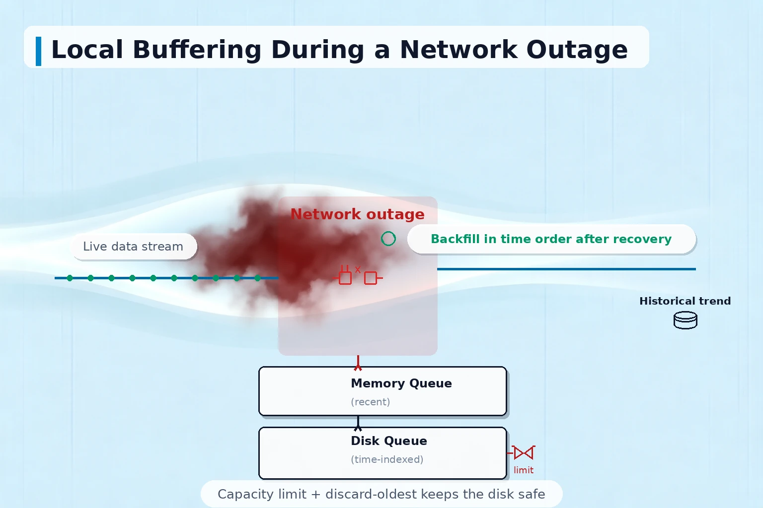
The value of store-and-forward is not how many records are stored, but whether, after recovery, the data returns to the historian in time order and joins the live record into one continuous curve.
The forwarding layer: what to send up, what to accept down
The forwarding layer faces MES, energy platforms and cloud services, and three matters should be settled with the upstream side in advance: what is sent, at what pace, and what happens when the link breaks.
| Item to agree | Common practice | What often gets missed |
|---|---|---|
| Data scope | Send by an agreed tag list rather than the whole database | Upstream receives unrelated tags and later blames the gateway side |
| Push cadence | Send on change plus a periodic fallback, with critical tags raised to a higher rate | Fixed intervals only, so brief spikes are all missed |
| Outage handling | After the upstream recovers, the gateway back-sends the backlog | No cap on backlog, so the recovery burst overwhelms the upstream |
Production commands travelling down to the machines should use the same channel: commands need permission and scope limits, and their execution results must be returned and logged, avoiding a one-way path that only sends.
How to check every point at acceptance
Acceptance of a collection system cannot rest on "numbers appear on the screen"; it has to return to the data itself.
- Full tag check: read every point against the tag list and compare with the field instrument display
- Outage drill: cut the link for a while, restore it, then verify the completeness and order of the backfilled data
- Continuous run: operate for a stretch of days and watch for silent failures and memory leaks
- Retention and export: history is kept for the agreed duration and exports in a format the upstream can parse directly
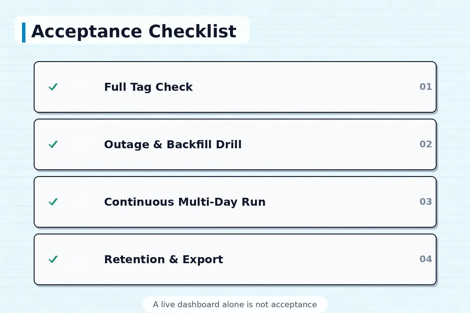
Only after these four items pass is the collection layer truly delivered; signing off on a live dashboard alone usually lets problems surface in bulk about three months later.
Information to prepare before the project starts
Sorting out the following in advance makes both the architecture and the quotation more accurate: controller models and communication conditions of the current machines, the instrument list with each device's protocol, the upstream system's requirements on scope and frequency, the workshop network conditions and available egress, and how long data may be retained locally during an outage. Put these in writing, and the discussion with an implementer becomes one about acceptance clauses rather than concepts.
Shanghai Chengxuan Intelligent has worked in industrial software and equipment connectivity since 2009, with product capability in data acquisition gateway software, protocol adaptation libraries and monitoring platforms, and an English-speaking contact for project discussion; we can confirm the boundary clauses of the five-layer architecture with you item by item, based on your equipment conditions and upstream requirements.
Summary
The value of a data acquisition gateway lies not in the single act of connecting machines, but in five layers — signal intake, protocol adaptation, data cleaning, outage buffering and forwarding — each with clear responsibilities and acceptance criteria. When the layer boundaries are written down at design time, adaptation rules live in configuration and outage drills are part of acceptance, adding machines, extending tag lists and changing upstream interfaces all involve far less rework, and shop-floor data becomes a foundation that MES and energy management can rely on.
Talk through your project
If you are evaluating shop-floor data collection or gateway selection, tell us your machine models, communication protocols and upstream system requirements, and we will suggest functional boundaries and an acceptance checklist for the five-layer architecture based on your actual conditions.
Contact Us