Chiller Plant Monitoring: Points and Sequencing
A chiller plant monitoring system collects the water loop, chiller and power data of a central plant onto one platform, stages chillers by load, modulates the bypass valve on differential pressure, and keeps alarms and energy figures as records you can query later. The point is not a good-looking screen. It is three concrete questions: how many chillers should run, is the water loop short of flow, and where does the electricity go. The sections below cover points, control, alarms and acceptance in that order.
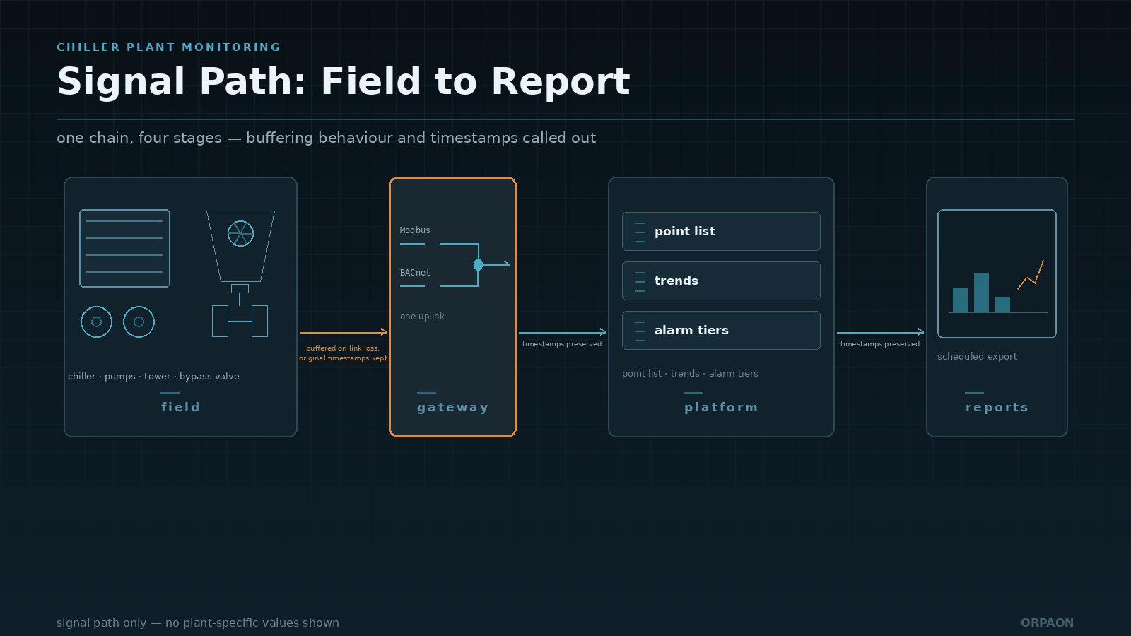
1. What the system covers: one water loop from plant to terminal
A chiller plant monitoring system collects status and parameters from chillers, chilled water pumps, condenser water pumps, cooling towers and bypass valves, decides the staging order by load, holds supply temperature, differential pressure and flow inside their set bands, and keeps a record of every alarm and every energy interval. Its boundary is see it, judge it, act on it: status acquisition, logic evaluation, alarm routing, reporting and remote operation belong to the system. The refrigerant cycle inside the chiller, the mechanical performance of the pumps and the insulation work on the piping do not, but faults in those areas still have to become visible through data.
Public statistics give a sense of scale. The IEA report The Future of Cooling (2018) states that air conditioners and electric fans account for about 20% of electricity used in buildings worldwide, or about 10% of total global electricity use. An IEA analysis published in 2025 puts electricity demand for space cooling at roughly 2,900 TWh, up about 50% since 2015. The central plant is where that demand concentrates, and the first value of monitoring is turning consumed kilowatt-hours into an accountable figure instead of a month-end estimate from a summary meter.
A common misjudgement is to treat plant monitoring as a graphics job: copy the chiller controller screens to the control room display and call it done. What actually determines the result is three things. Whether the point list covers both ends of the water loop, meaning supply and return temperature, differential pressure and flow. Whether staging follows load rather than a fixed time schedule. Whether data stays continuous across a network drop or a platform restart. The screen is the output. Those three are the engineering work.
2. How to build the point list: five object types, four parameter families
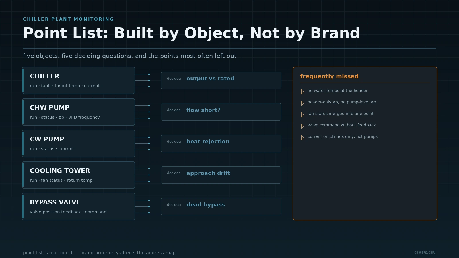
Build the point list by object, not by brand. A single plant may run chillers from two vendors, one speaking BACnet and the other Modbus, but the physical quantities you need to judge are the same: is this machine running, how much cooling did it deliver, how much electricity did it draw, and is the water path open. Define the quantities by object first, then negotiate how each device exposes them. That order gives the interface discussion a basis.
| Object | Points to collect | What it decides | Frequent omission |
|---|---|---|---|
| Chiller | Run status, fault dry contact, chilled water in/out temperature, condenser water in/out temperature, current or power | Deviation of actual output from rated capacity, short cycling | Run status only, no water temperatures, so cooling load cannot be calculated |
| Chilled water pump | Run/fault, VFD frequency or current, suction-discharge pressure difference | Whether flow is short, whether frequency matches actual load | Pressure difference measured only on the header, so single-pump efficiency cannot be compared |
| Condenser water pump | Run/fault, current, condenser return water temperature | Whether heat rejection is normal, whether the pump is running dry | Tower fan status merged into the same point |
| Cooling tower | Fan run status, leaving water temperature, make-up water flow | Whether approach temperature is drifting, whether fill or distribution is fouled | Fan status only, no water temperatures |
| Bypass valve and header | Valve position feedback, header differential pressure, total flow, supply and return temperature | Whether the bypass is acting without effect, whether terminals are short of flow | Command issued without position feedback |
Set sampling rates by purpose; not everything needs a one-second interval. Chiller and pump run status and fault signals are sampled per second because they drive interlocks and alarms. Temperature and differential pressure are sampled every ten seconds to a minute for trends and control. Energy and cooling output accumulate per minute or per fifteen minutes for accounting and reports. Every analogue point needs range, engineering unit, filter time and a wire-break threshold written into the point list. If the engineering range behind a 4-20 mA signal is not documented, the next person to calibrate it will shift the reading.
3. Control sequence: stage by load, bypass by differential pressure
The goal of sequencing is not to run fewer machines. It is to keep the running machines inside a reasonable operating band. Use load ratio as the criterion, not the clock: calculate current cooling demand from header flow and supply-return temperature difference, compare it with the rated capacity of the machines online, add a machine when demand exceeds the modulating range of what is running, and drop one when demand stays below the rated output of a single machine for a sustained period. A time schedule can assist, but it cannot lead, because the load curve in shoulder season looks nothing like midsummer.
- Staging criterion: base the decision on cooling demand divided by the rated output of machines online, with a sustained-time delay so that a transient load swing does not cause short cycling.
- Pump interlock: start the matching chilled water pump and confirm differential pressure is established before the chiller starts, and reverse the order on stop. Measure the minimum VFD frequency during commissioning rather than copying a datasheet value.
- Bypass control: use header differential pressure as the primary controlled variable, with valve position and flow as limits. When terminal load falls, close the bypass first and consider dropping a machine afterwards.
- Minimum flow protection: chillers have a minimum flow requirement. Force the bypass open when flow falls below the limit to avoid evaporator freeze-up and low-pressure trips.
- Condenser side coordination: stage tower fans on leaving water temperature and approach, pair condenser water pumps one-to-one with chillers, and avoid a high condensing temperature that pulls efficiency down.
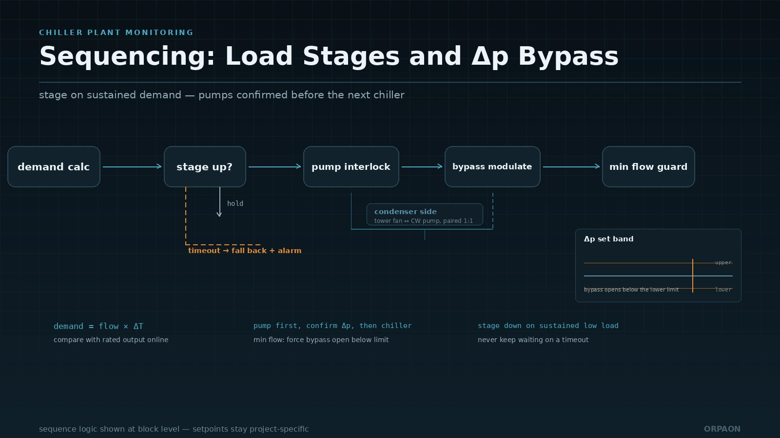
Write the sequence as a state machine during design, not as fragments scattered across program sections. Each state needs an entry condition, an exit condition and a timeout action. If a stage-up request is issued and differential pressure is not established within a defined time, the sequence should fall back and raise an alarm rather than keep waiting. Most plant incidents are not single-point failures; they are sequences with no exit on the abnormal branch.
4. Alarms, data quality and acceptance
A common way to make a plant alarm system useless is to route everything to everyone. Chiller faults, pump faults, low differential pressure, high temperature and communication loss arrive together, operators become desensitised within days, and the one alarm that needed action is buried. Tier alarms by consequence rather than by equipment: anything that stops a machine or threatens cooling goes to tier one, anything that hurts efficiency but can wait goes to tier two, and anything recorded only goes to tier three. Each alarm needs a trigger condition, an acknowledge method and a reset condition written down.
Data quality decides whether the system is trusted. Buffer locally during a network drop and backfill after recovery, and stamp backfilled records with the original timestamp rather than the ingest time. After a platform restart, trend curves should be continuous with no gaps. With buffering and timestamp alignment, the month-end energy report reconciles against the meter. Without them, the report is indicative only. At acceptance this engineering detail matters far more than how the screen looks.
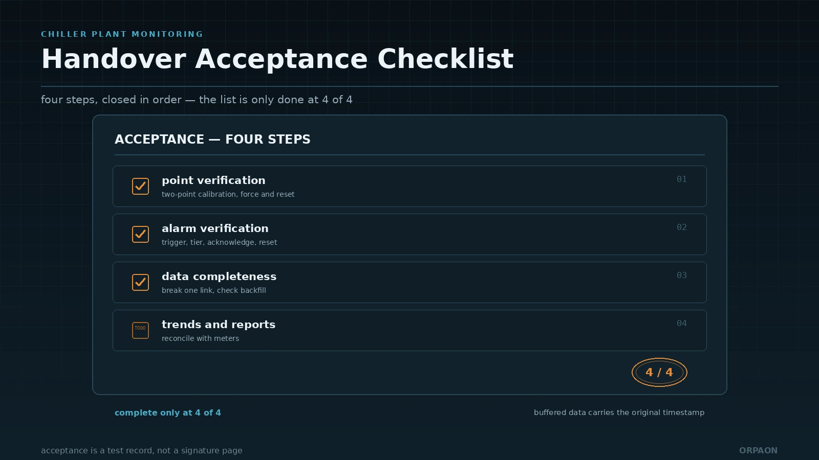
Run acceptance in four steps, each with an inspectable output:
- Point verification: walk the point list against live signals, perform a two-point calibration on every analogue input, and force and reset every digital point once.
- Alarm verification: trigger every alarm at least once, then check routing, tier, acknowledgement and reset records.
- Data completeness: break one communication path on purpose, confirm buffering and backfill work, and check that the trend stays continuous.
- Trends and reports: after a period of running, export energy and cooling reports and reconcile them against the electricity meter and the cooling meter.
Several standards are directly quotable. ASHRAE Guideline 22-2012 provides a method for instrumenting central chilled water plants. AHRI 550/590 (I-P) and 551/591 (SI) define the rating conditions for chiller performance, so measured efficiency must be converted to the same conditions before comparison. ISO 50001:2018 requires traceable data sources for energy performance parameters, and plant cooling output and electricity consumption are exactly such parameters. For equipment using fluorinated refrigerants, Regulation (EU) 2024/573 sets leak-check and record requirements, so refrigerant-related parameters and service records in the monitoring system should line up with them.
Settle the points and the water loop first, then automate
The hard part of plant monitoring is not software. It is whether the design stage settled the water loop relationships, the purpose of each point and the abnormal branches. Build the point list by object, judge staging by load, tier alarms by consequence and accept in four steps, and the system will still be readable and adjustable by whoever takes over three years later. Do the screens first and the logic later, and you will rework through commissioning.
Shanghai Orpaon Intelligent has built monitoring systems for manufacturing and building energy since 2009, including facility monitoring that unifies water, power, gas, HVAC and wastewater, and energy SCADA for factories and buildings covering AHUs, heating and cooling sources and compressed air stations, with overseas factory deliveries using Chinese, English and Japanese interfaces on a redundant OPC UA architecture. Chiller plant monitoring can be developed to match existing equipment and communication conditions, or delivered as a subsystem of an energy management platform.
Book a chiller plant monitoring review
If your central plant is being retrofitted or newly built, bring the communication methods and point list of the existing equipment. We will return a recommended point and control-logic list based on your water loop.
Contact Us